Project 1: Rasterizer

前言
第一个project的内容覆盖CS184从spring2019第一课到第五课的内容,包含了三角形光栅化
绘制,基本的矩阵变换和采样。总共是两个Section,七个part,由于第七个part属于个人自由
发挥选做内容。。本人由于懒没有做,因此只有前六个part。Project1采用了CS184教学团队
自己开发的GUI和图形库CGL,貌似是在OpenGL上封装了一层。详细的初始化说明请参考README.md。完整的参考实现请访问我的git repo。
Section I: Rasterization
Part 1: Rasterizing single-color triangles
题目介绍
第一部分是光栅化三角形。这貌似是每个图形学入门课程开始必做的一个练习。
在开始之前,建议先看一下这篇文章,讲述了图片如何以数据形式存在于计算机中。
本题的目标是给定每个像素点,判断是否在三角形之内,如果是则将传入的颜色赋值给该像素点。
只需要修改两个函数。
(1)SampleBuffer::fill_color in drawrend.h
(2)DrawRend::rasterize_triangle in drawrend.cpp
实现原理
其中 SampleBuffer::fill_color 函数用来填充一个sub-pixel的颜色,如下所示。
解释一下其中的几个变量。
- Intuitively, a sample buffer instance is a pixel,
- or (samples_per_side x samples_per_side) sub-pixels.
根据注释一个SampleBuffer代表一个采样区域(一开始是一个pixel)。后面这个采样区域会
变成由多个sub-pixel组成。sub_pixels[i][j]表明第i行第j个sub-pixel,对于本题来说
i和j一直是0(因为只有一个像素)。这个函数的修改很简单,将sub_pixels数组代表的sub-pixel填充好给定的颜色即可。
但是要注意PixelColorStorage,其声明如下,这个数组中每个元素表示三通道RGB中一个通道的颜色值,每个元素值大小在0-255。
typedef std::vector<unsigned char> PixelColorStorage;从其初始化可以看出来,这是一个长度为3的数组,白色就是(255, 255, 255)。
PixelColorStorage white = std::vector<unsigned char>(3, 255);SampleBuffer 还有两个数据成员,即sub_pixels和表示sub-pixel边长的samples_per_side。
    std::vector<std::vector<PixelColorStorage> > sub_pixels;
size_t samples_per_side;我们要补完的fill_color函数如下。在图片初始化解析的过程中,颜色值被全部而Color中r,g,b三个值都是float并且限制在[0,1]的大小,因此我们需要先乘上255在做一个类型转换。否则图片就会是全黑的。
    void SampleBuffer::fill_color(int i, int j, Color c) {
      PixelColorStorage &p = sub_pixels[i][j];
      if(p.size() != 3)
      {
        std::cout<<"PixelColorStorage没有初始化!"<<endl;
      }
      else
      {
        p[0] = (uint8_t)(c.r * 255);
        p[1] = (uint8_t)(c.g * 255);
        p[2] = (uint8_t)(c.b * 255);
      }
}然后就是我们的重头戏了,DrawRend::rasterize_triangle 函数,这个绘制三角形的函数将会贯穿整个project。首先我们来看函数的参数,x0,y0,x1,y1,x2,y2分别是三角形的三个顶点。color则是指定的颜色。每个要显示到屏幕上的三角形都会调用一次这个函数,在该函数中使该三角形内的像素点显示成指定的color。
void DrawRend::rasterize_triangle( float x0, float y0,
float x1, float y1,
float x2, float y2,
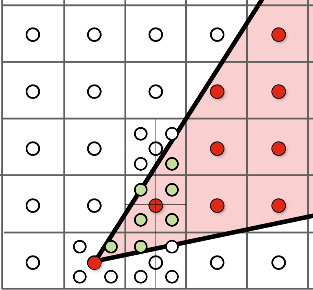
Color color, Triangle *tri) {核心是判断点是否位于三角形之内,我的做法是分别取x坐标和y坐标的最大最小值,形成三角形的外接长方形,然后对于这个长方形内的每个点进行逐步的判断,如果位于三角形之内就赋值相应的颜色,否则什么都不做(默认是白色)。这里是存在很大的优化空间的,但是我由于懒暂时没有做。。。。
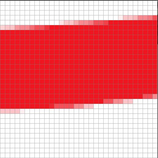
三角形内部判定方程如下,值得注意的是,传入的点是没有默认的顺序的,可能是顺时针也可能是逆时针。
由于我们的判定方法是 每个像素点对应的向量 与 每条边的法向量叉乘,如果全部大于等于零(即sin夹角小于等于90°,此时法向量应该是朝向三角形内部)表示在三角形之内,但实际上换一个顺序(即法向量指向三角形之外),此时只有当叉乘结果全部小于等于零才是在三角形之内的。
示意图如下。
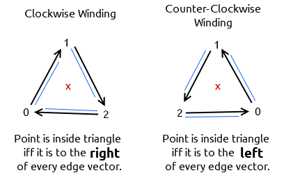
如果没有考虑到顺逆时针的问题,运行出来的结果就会像下图这样。
三角形内部判定公式如下
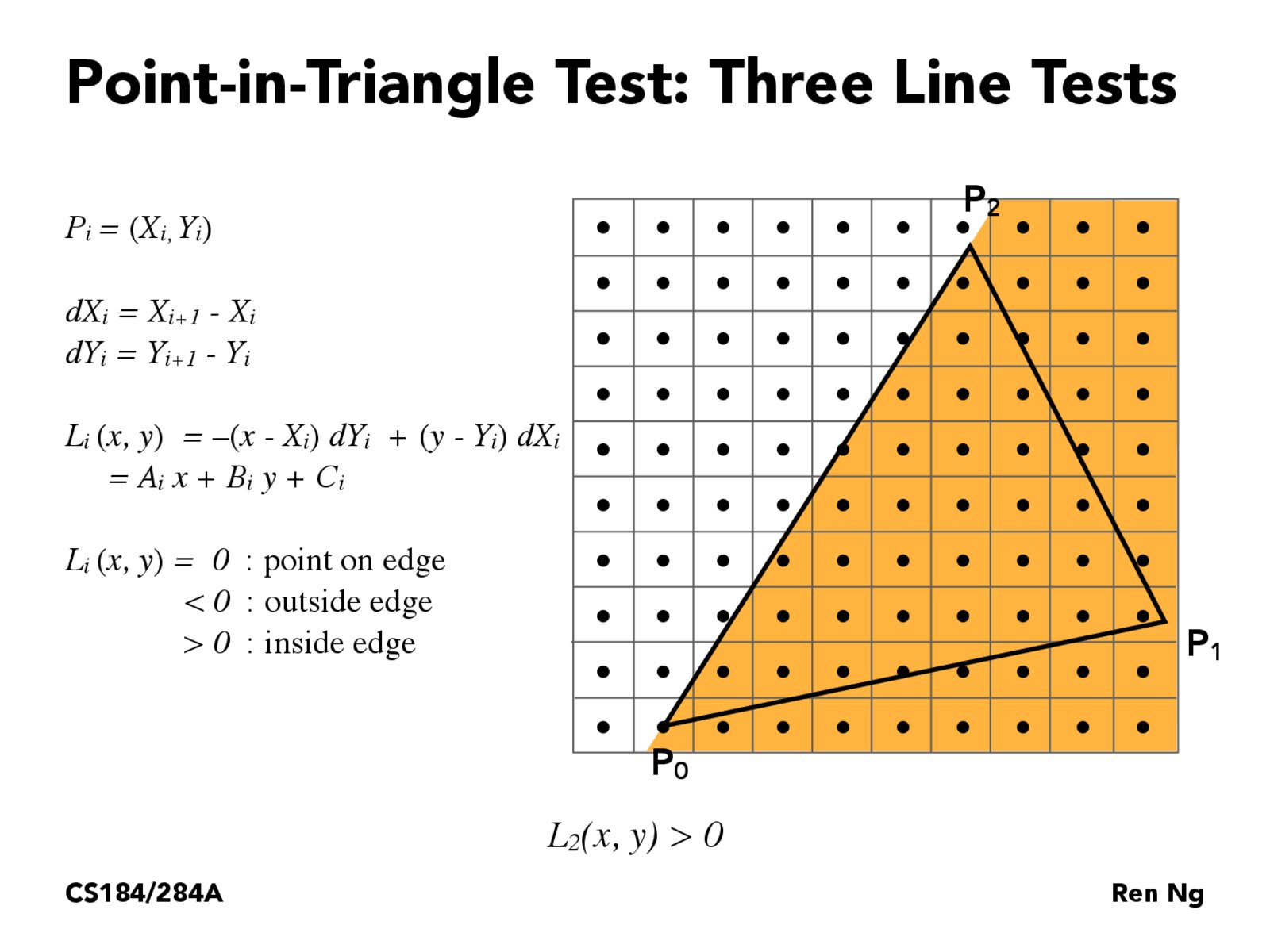
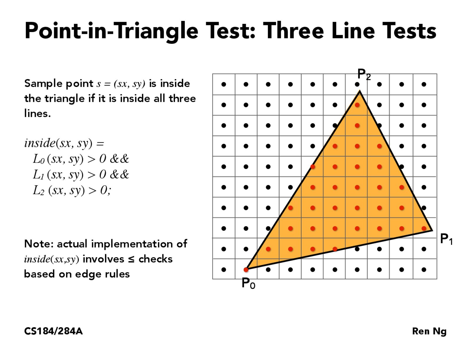
完整的实现如下。
void DrawRend::rasterize_triangle( float x0, float y0,
float x1, float y1,
float x2, float y2,
Color color, Triangle *tri) {
float xMax = std::max(x0, x1);
xMax = std::max(xMax, x2);
float yMax = std::max(y0, y1);
yMax = std::max(yMax, y2);
float xMin = std::min(x0, x1);
xMin = std::min(xMin, x2);
float yMin = std::min(y0, y1);
yMin = std::min(yMin, y2);
float dx_10 = x1 - x0;
float dx_21 = x2 - x1;
float dx_02 = x0 - x2;
float dy_10 = y1 - y0;
float dy_21 = y2 - y1;
float dy_02 = y0 - y2;
for (int x = (int)xMin; x < (int)xMax; x++)
{
for (int y = (int)yMin; y < (int)yMax; y++)
{
float xCenter = x + 0.5f;
float yCenter = y + 0.5f;
int isInside = 0;
if (-dy_10 * (xCenter - x0) + dx_10 * (yCenter - y0) >= 0)
isInside++;
if (-dy_21 * (xCenter - x1) + dx_21 * (yCenter - y1) >= 0)
isInside++;
if (-dy_02 * (xCenter - x2) + dx_02 * (yCenter - y2) >= 0)
isInside++;
if (isInside == 0 || isInside == 3)
{
int xInt = x;
int yInt = y;
if (yInt >= 0 && yInt < samplebuffer.size() && xInt >= 0 && xInt < samplebuffer[yInt].size())
samplebuffer[yInt][xInt].fill_pixel(color);
}
}
}
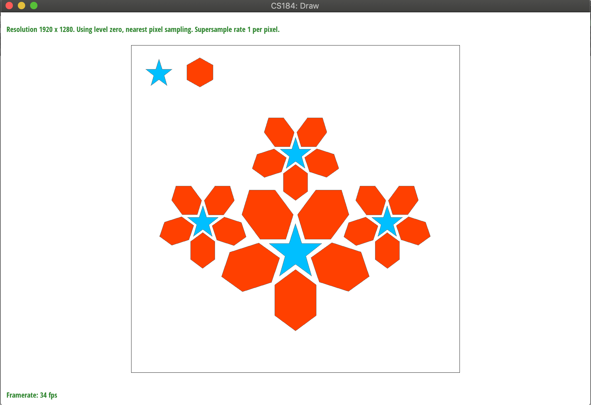
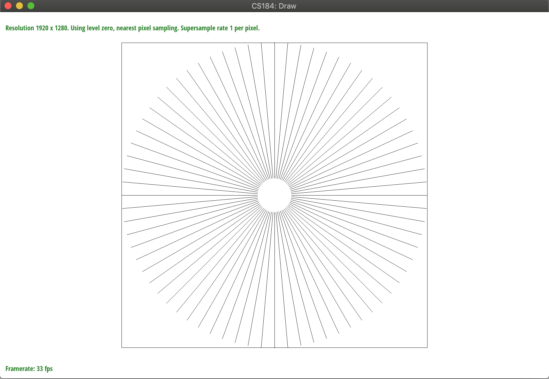
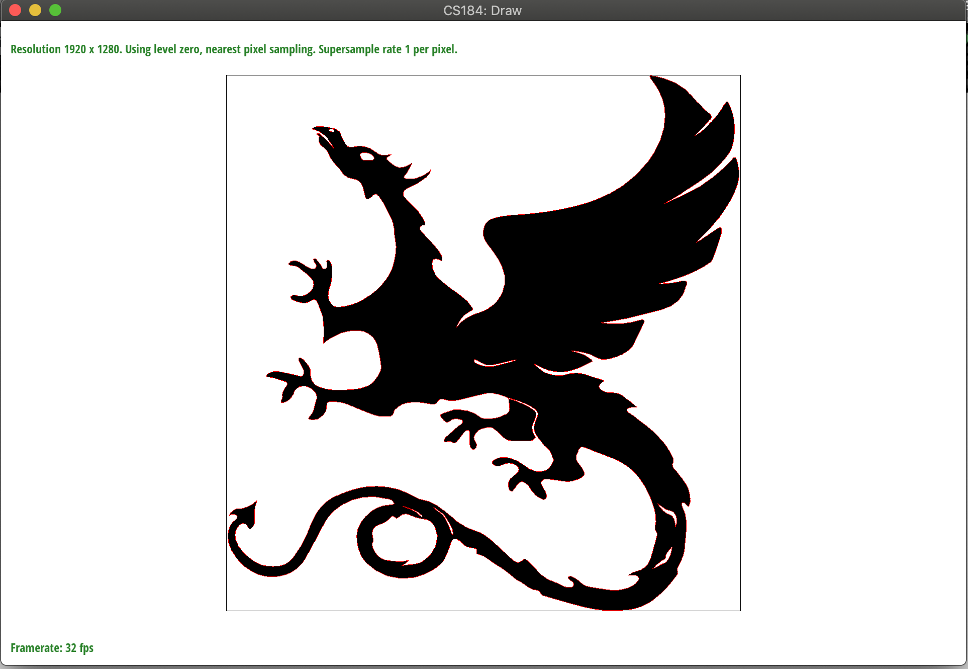
}编译之后在cmake-build-debug文件下于命令行输入./draw ../svg/basic 就可以看到结果。
如果看到下图这样的结果那么就恭喜你,第一题完成啦!
### Part 2: Antialiasing triangles #### 题目介绍 第二部分让我们实现反走样(antialiasing),至于走样为什么会产生,由于没有学过信号处理对于这部分比较模糊,我只知道大概是由于临近像素点颜色差比较大的地方体现出来就是高频的部分,而如果图像的频率高于奈奎斯特频率(也就是采样频率的一半),就会出现图形彼此交叠失真的现象,下图展示了走样(混叠)和采用反走样后的图片。
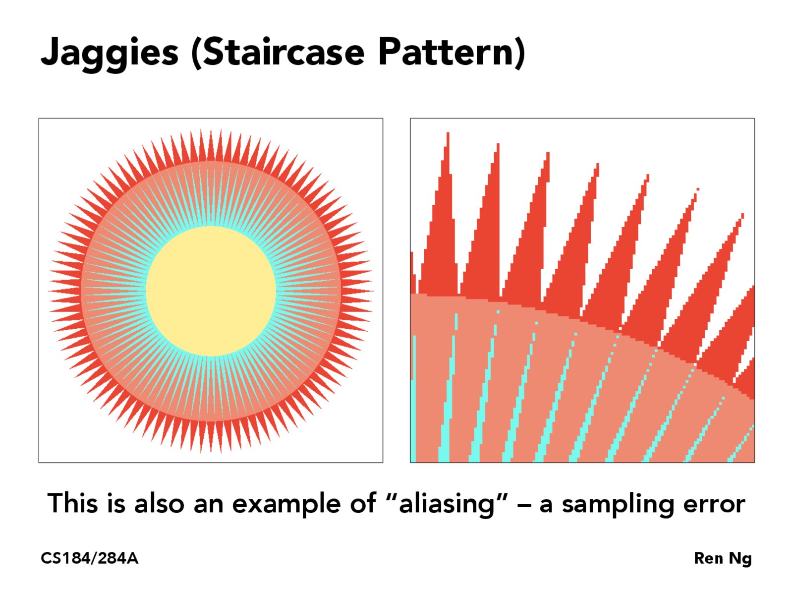
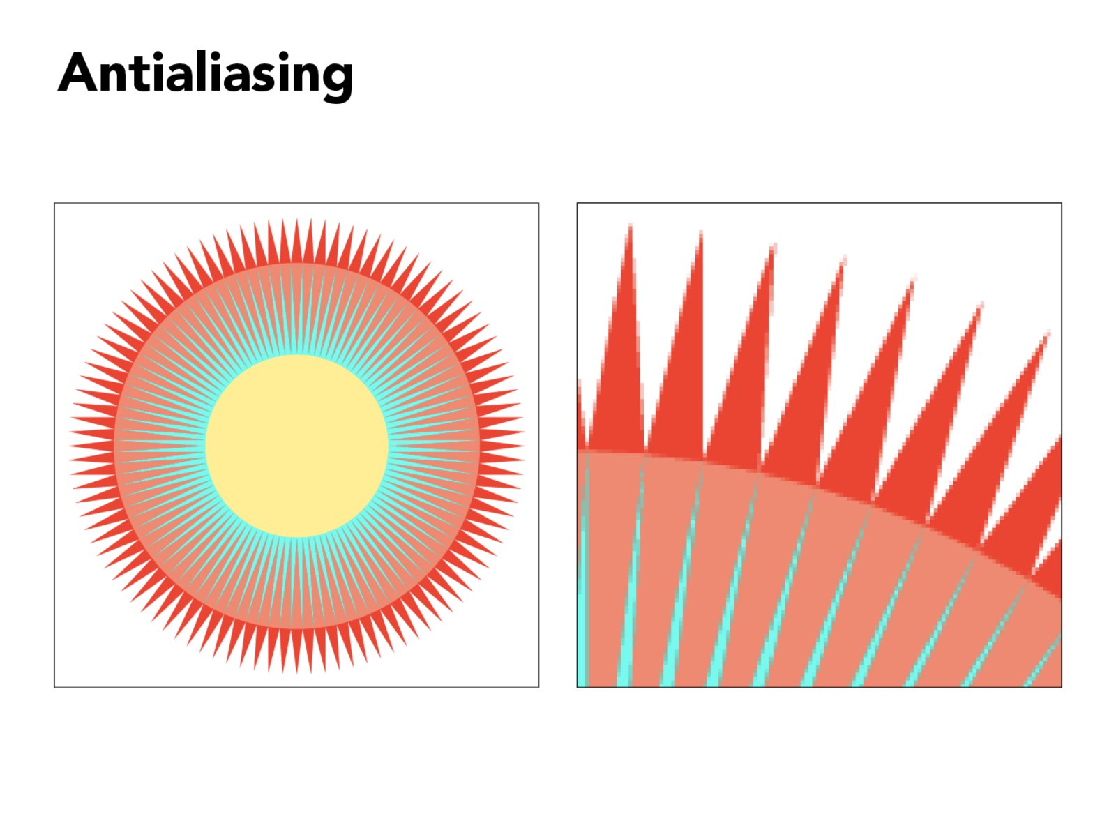
具体的理论我也不清楚,可以参考下[知乎上更详尽的一种解释](https://zhuanlan.zhihu.com/p/28800047)。
回到我们的题目上来,我们要实现反走样,最最基本的方法就是super-sampling,字义上来看是超采样,wiki上翻译成反锯齿,如上图所示也很直观。就是我们将采样点增大,比方说一个像素分成四个子像素sub-pixel,然后对每个子像素采样,最后取一个平均值赋值给该像素。这样整个图形就会变得柔和一些,锯齿会减少。
实现原理
本题中我们将每个像素分成samples_per_side * samples_per_side个子像素,其中samples_per_side就是边长。
需要修改以下两个函数 (1)`DrawRend::rasterize_triangle`
(2)`SampleBuffer::get_pixel_color` in `drawrend.h`
其中get_pixel_color返回一个像素的平均颜色。代码如下
    Color get_pixel_color()
    {
      if(samples_per_side == 1)
      {
          return Color(sub_pixels[0][0].data());
      }

      Color arrangeColor = Color();
      for(int i = 0; i < samples_per_side; i++)
      {
        for(int j = 0; j < samples_per_side; j++)
        {
            try
            {
                PixelColorStorage &p = sub_pixels[i][j];

                arrangeColor += Color((float)p[0] / 255, (float)p[1] / 255, (float)p[2] / 255);
            }
            catch (int x)
            {
                std::cout<<"sub_pixels的长度与samples_per_side不相等!"<<std::endl;
            }

        }
      }

      arrangeColor.r /= samples_per_side * samples_per_side;
      arrangeColor.g /= samples_per_side * samples_per_side;
      arrangeColor.b /= samples_per_side * samples_per_side;
      return arrangeColor;
    }
而在渲染三角形的`DrawRend::rasterize_triangle`函数中,我们同样需要做一些修改。核心就是我添加了两个循环,遍历像素内的每个子像素,对子像素进行三角形内部判定,然后调用`fill_color`函数填充每个子像素sub-pixel的颜色而不是像上一题那样直接调用`fill_pixel`填充满整个像素。 你可能会问,那我们刚才实现的`get_pixel_color`用来干嘛呢?请参照project文档说明,里面说`get_pixel_color`会在绘制完之后统一调用,给每个像素取平均色。
void DrawRend::rasterize_triangle( float x0, float y0,
                         float x1, float y1,
                         float x2, float y2,
                         Color color, Triangle *tri) {

  float xMax = std::max(x0, x1);
  xMax = std::max(xMax, x2);
  float yMax = std::max(y0, y1);
  yMax = std::max(yMax, y2);
  float xMin = std::min(x0, x1);
  xMin = std::min(xMin, x2);
  float yMin = std::min(y0, y1);
  yMin = std::min(yMin, y2);

  float dx_10 = x1 - x0;
  float dx_21 = x2 - x1;
  float dx_02 = x0 - x2;
  float dy_10 = y1 - y0;
  float dy_21 = y2 - y1;
  float dy_02 = y0 - y2;

  for (int x = (int)xMin; x <= (int)xMax; x++)
  {
      for (int y = (int)yMin; y <= (int)yMax; y++)
      {
          if (y < 0 || y >= samplebuffer.size() || x < 0 || x >= samplebuffer[y].size())
              continue;

          const SampleBuffer &p = samplebuffer[y][x];
          for(int sub_x = 0; sub_x < p.samples_per_side; sub_x++)
          {
            for(int sub_y = 0; sub_y < p.samples_per_side; sub_y++)
            {
              float centerLength = (1.0f / p.samples_per_side);
              float xCenter = x + centerLength * (sub_x + 1) - centerLength / 2;
              float yCenter = y + centerLength * (sub_y + 1) - centerLength / 2;

              int isInside = 0;
              if (-dy_10 * (xCenter - x0) + dx_10 * (yCenter - y0) >= 0)
                isInside++;
              if (-dy_21 * (xCenter - x1) + dx_21 * (yCenter - y1) >= 0)
                isInside++;
              if (-dy_02 * (xCenter - x2) + dx_02 * (yCenter - y2) >= 0)
                isInside++;

              if (isInside == 0 || isInside == 3) {
                samplebuffer[y][x].fill_color(sub_x, sub_y, color);
              }
            }
          }
      }
  }
}
运行后结果如下,可以看到随着采样率的提升,锯齿逐渐减弱。
Part 3: Transforms
题目介绍
第三部分是关于矩阵变换的,这个部分比较简单,只要写好三个变换矩阵就OK了,分别是缩放矩阵,平移矩阵和旋转矩阵。具体的公式证明和讲解请参照这个PPT和这个PPT。
实现原理
只需要修改transform.cpp下的三个函数。
(1)translate
(2)scale
(3)rotate
Matrix3x3 translate(float dx, float dy) {
    return Matrix3x3(1, 0, dx,
                     0, 1, dy,
                     0, 0, 1);
}

Matrix3x3 scale(float sx, float sy) {
    return Matrix3x3(sx, 0, 0,
                     0, sy, 0,
                     0, 0, 1);
}

Matrix3x3 rotate(float deg) {
    float pi = 3.141592;
    float rad = (deg / 180) * pi;
    return Matrix3x3(cos(rad), -sin(rad), 0,
                     sin(rad), cos(rad), 0,
                     0 ,0, 1);
}
运行后结果如下

Section II: Sampling
Part 4: Barycentric coordinates
题目介绍
随后我们来到了第二个Section采样。Part4是重心坐标,让我们先来看一下什么是重心坐标,简短的说在我们的例子中,给定三角形的三个坐标A,B,C和对应的Color,然后对于三角形内一点P,我们可以确定三个系数,α,β,γ满足α+β+γ = 1,α*A + β*B + γ*C 就是点P的重心坐标。当然重心坐标没什么用,对我们来说将坐标替换成三个顶点对应的颜色,那么我们就得到了点P在三角形内的颜色插值结果。也就是说我们的根本目的是利用重心坐标系数获取三角形内一点P的插值颜色
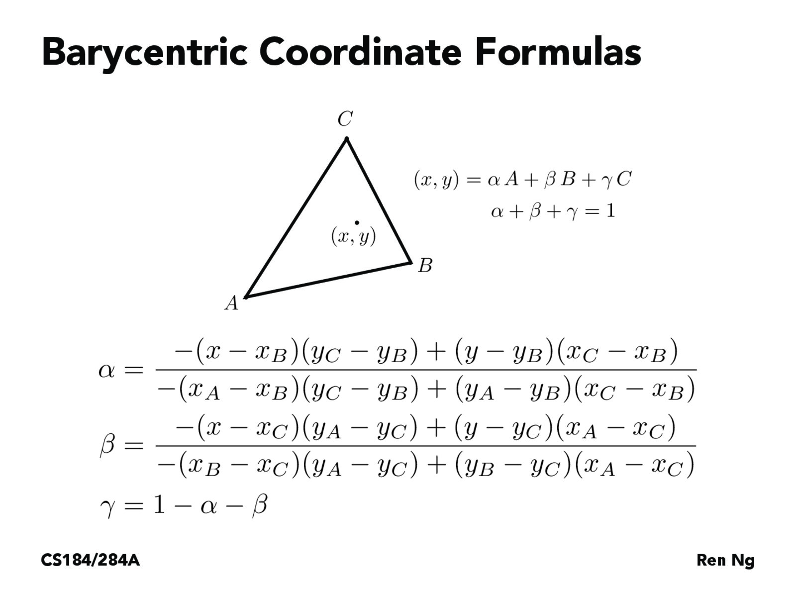
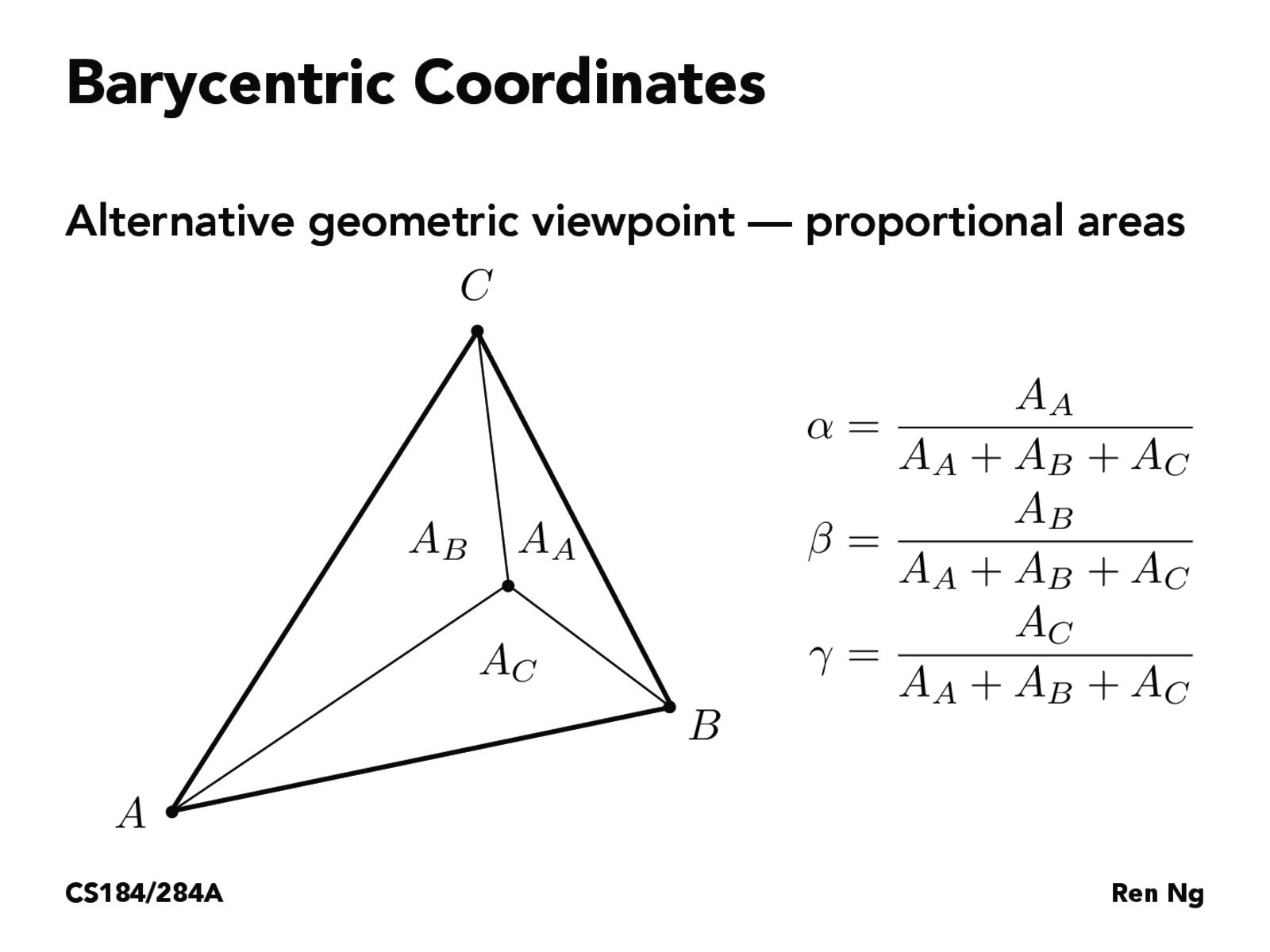
至于如何获取α,β,γ这三个系数,使用如下所示的公式,本质上三个系数之比就是三个顶点与P组成的三个三角形面积之比。(注:以α为例,分子是将点P带入直线方程BC,分母是将点A带入直线方程BC,实际上α就是△BPC和△ABC面积之比)
实现原理
在本题需修改如下两个函数
(1)DrawRend::rasterize_triangle
(2)ColorTri::color in svg.cpp
除了我们的老朋友DrawRend::rasterize_triangle以外,还需要完成ColorTri::color以获取我们的插值颜色。如果你一路做到这里,你一定会注意到在三角形渲染函数中,Triangle类型的参数*tri一直没有用到,直到这个部分才开始用到。查看Triangle中的声明我们可以看到。
struct Triangle : SVGElement {

  Triangle(): SVGElement (TRIANGLE ) { }
  Vector2D p0_svg, p1_svg, p2_svg;

  void draw(DrawRend *dr, Matrix3x3 global_transform);
  virtual Color color(Vector3D p_bary, Vector3D p_dx_bary = Vector3D(), Vector3D p_dy_bary = Vector3D(),
                        SampleParams sp = SampleParams()) = 0;
};
包含了三角形的三个顶点(注意这三个顶点没有经过全局变换,所以不能用!)
而我们将修改的另外一个函数ColorTri::color则来自于继承自Triangle的ColorTri。
在ColorTri中我们可以直接使用三个顶点的颜色
struct ColorTri : Triangle {

  Color color(Vector3D p_bary, Vector3D p_dx_bary = Vector3D(), Vector3D p_dy_bary = Vector3D(),
                        SampleParams sp = SampleParams());

  Color p0_col, p1_col, p2_col;
};
因此`ColorTri::color`函数的实现如下,将存有三个重心坐标系数的`p_bary`与三个顶点的颜色分别相乘
Color ColorTri::color(Vector3D p_bary, Vector3D p_dx_bary, Vector3D p_dy_bary, SampleParams sp) {
  return Color(p_bary[0] * p0_col + p_bary[1] * p1_col + p_bary[2] * p2_col);
}
为了计算重心坐标系数,我在`drawrend.cpp`里添加了两个函数
float LineEquation(float x, float y, float x1, float y1, float x2, float y2)
{
    return (-(x - x1) * (y2 - y1) + (y - y1) * (x2 - x1));
}

bool DrawRend::bary_coord(float x, float y, float x0, float y0, float x1, float y1, float x2, float y2, float* params)
{
    float alpha, beta, gamma;
    alpha = params[0] = LineEquation(x, y, x1, y1, x2, y2) / LineEquation(x0, y0, x1, y1, x2, y2);
    beta = params[1] = LineEquation(x, y, x2, y2, x0, y0) / LineEquation(x1, y1, x2, y2, x0, y0);
    gamma = params[2] = 1 - params[0] - params[1];

    return true;
}之后修改我们的老朋友,如果tri非空就计算获得重心坐标系数然后调用ColorTri::color函数获取颜色,之后就和之前一样了。
void DrawRend::rasterize_triangle( float x0, float y0,
float x1, float y1,
float x2, float y2,
Color color, Triangle *tri) {
float xMax = std::max(x0, x1);
xMax = std::max(xMax, x2);
float yMax = std::max(y0, y1);
yMax = std::max(yMax, y2);
float xMin = std::min(x0, x1);
xMin = std::min(xMin, x2);
float yMin = std::min(y0, y1);
yMin = std::min(yMin, y2);
float dx_10 = x1 - x0;
float dx_21 = x2 - x1;
float dx_02 = x0 - x2;
float dy_10 = y1 - y0;
float dy_21 = y2 - y1;
float dy_02 = y0 - y2;
// add for part4
bool isBary = false;
if(tri != nullptr)
isBary = true;
for (int x = (int)xMin; x <= (int)xMax; x++)
{
for (int y = (int)yMin; y <= (int)yMax; y++)
{
if (y < 0 || y >= samplebuffer.size() || x < 0 || x >= samplebuffer[y].size())
continue;
const SampleBuffer &p = samplebuffer[y][x];
for(int sub_x = 0; sub_x < p.samples_per_side; sub_x++)
{
for(int sub_y = 0; sub_y < p.samples_per_side; sub_y++)
{
float centerLength = (1.0f / p.samples_per_side);
float xCenter = x + centerLength * (sub_x + 1) - centerLength / 2;
float yCenter = y + centerLength * (sub_y + 1) - centerLength / 2;
int isInside = 0;
if (-dy_10 * (xCenter - x0) + dx_10 * (yCenter - y0) >= 0)
isInside++;
if (-dy_21 * (xCenter - x1) + dx_21 * (yCenter - y1) >= 0)
isInside++;
if (-dy_02 * (xCenter - x2) + dx_02 * (yCenter - y2) >= 0)
isInside++;
if (isInside == 0 || isInside == 3) {
if(!isBary)
samplebuffer[y][x].fill_color(sub_x, sub_y, color);
else
{
float params[3] = {1, 1, 1};
if(!this->bary_coord(x, y, x0, y0, x1, y1, x2, y2, params))
{
samplebuffer[y][x].fill_color(sub_x, sub_y, color);
return;
}
Vector3D v3(params[0], params[1], params[2]);
Color cc = tri->color(v3);
samplebuffer[y][x].fill_color(sub_x, sub_y, cc);
}
}
}
}
}
}
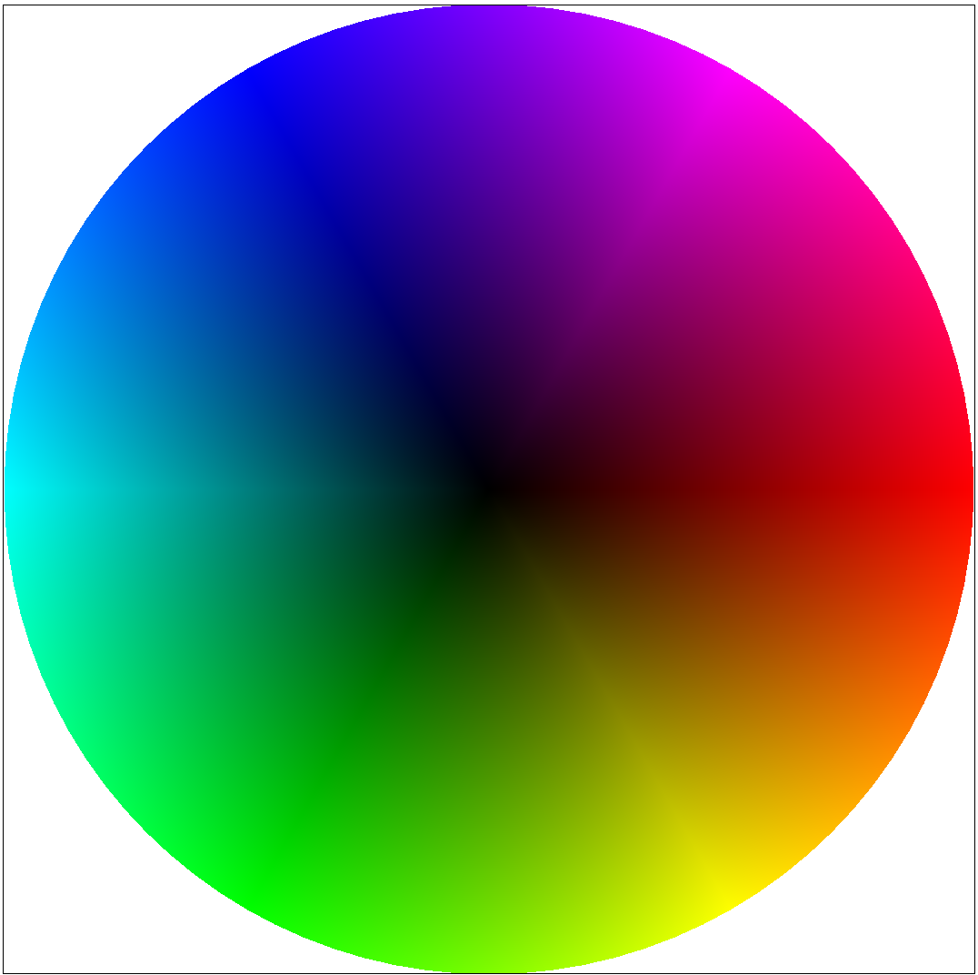
}运行之后,test7就可以正常显示了,结果如下
Part 5: “Pixel sampling” for texture mapping
题目介绍
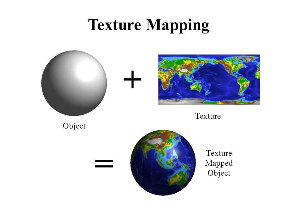
到Part5我们正式进入纹理映射的内容。这一题中我们将通过实现数据结构TexTri和Texture相关的函数实现texture mapping(纹理映射)。纹理映射说来就是一个映射过程,对于surface上的每个像素点找到对应纹理的纹素点。通俗的讲,纹理是一张2D的图片,而surface表面可能是3D的也可能是2D的,纹理映射的过程就是将纹理图包裹到这个表面上。
实现原理
我们需要修改的函数如下。
(1)DrawRend::rasterize_triangle
(2)TexTri::color
(3)Texture::sample
(4)Texture::sample_nearest
(5)Texture::sample_bilinear
首先在DrawRend::rasterize_triangle中创建一个SampleParams,将drawrend类的成员变量psm和lsm赋值给SampleParams中对应成员。与上一题一样,我们一样计算了重心坐标系数然后接着我们调用tri->color函数,我们通过重心坐标系数计算像素点对应的纹理坐标。
Color TexTri::color(Vector3D p_bary, Vector3D p_dx_bary, Vector3D p_dy_bary, SampleParams sp) {

  Vector2D tex_point = p_bary[0] * p0_uv + p_bary[1] * p1_uv + p_bary[2] * p2_uv;
  sp.p_uv = tex_point;
  return tex->sample(sp);
}
随后调用sample函数进行纹理采样。其中levelD我们暂时不用管默认设置为0就行。
Color Texture::sample(const SampleParams &sp) {

    float levelD = 0;
    if (sp.psm == P_NEAREST)
    {
      return this->sample_nearest(sp.p_uv, (int)levelD);
    }
    else
    {
      return this->sample_bilinear(sp.p_uv, (int)levelD);
    }

    return Color();
}
接着我们根据指定的psm也就是pixel sample method像素采样方法调用对应函数。下面介绍一下两种采样方法,最邻近采样和双线性采样。最邻近采样很直接,由于uv.x和uv.y是属于`[0,1]`的,因此乘上纹理贴图的长和宽之后才是真正的纹理坐标,但是得到的数可能不是整数,因此我们直接转型后返回该纹理坐标对应的颜色即可。
Color Texture::sample_nearest(Vector2D uv, int level) {
      if (level >= mipmap.size() || level < 0)
      {
          std::cout << "level越界了! 此时的level大小是:" <<level<<" 坐标是:"<<uv<<std::endl;
          return Color();
      }
      int tx = static_cast<int>(uv.x * mipmap[level].width);
      int ty = static_cast<int>(uv.y * mipmap[level].height);
      return mipmap[level].get_texel(tx, ty);
}
双线性采样则略显复杂,实际上就是连续采样两次,分别在X方向和Y方向上。对采样点四周的四个点进行两两线性插值得到结果。下图中的t和s是比例,其中`t = (y - u00.y) / (u01.y - u00.y)`,`s = (x - u00.x) / (u10.x - u00.x))`。
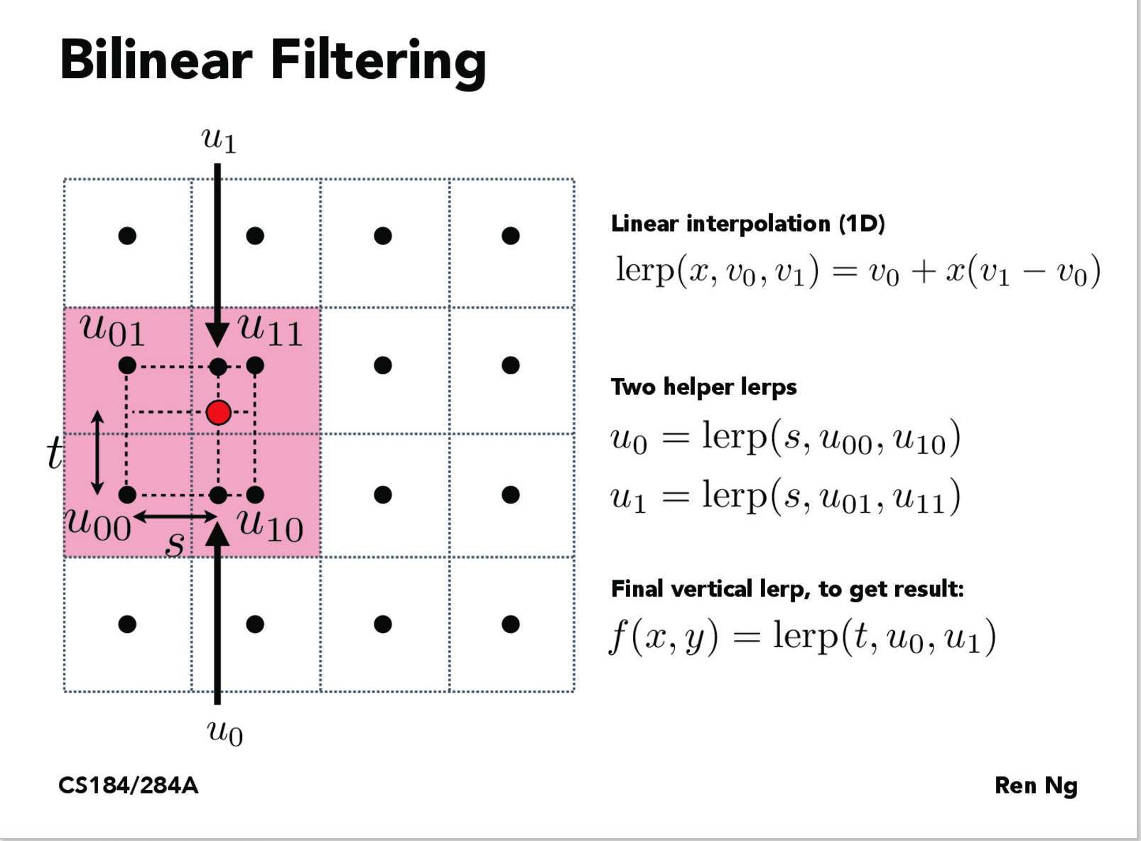
代码如下所示。
Color Texture::sample_bilinear(Vector2D uv, int level) {
      if (level >= mipmap.size() || level < 0)
      {
          std::cout << "level越界了! 此时的level大小是:" <<level<<" 坐标是:"<<uv<<std::endl;
          return Color();
      }
      float tx = static_cast<float>(uv.x * mipmap[level].width);
      float ty = static_cast<float>(uv.y * mipmap[level].height);

      int x0 = static_cast<int>(floor(tx));
      int y0 = static_cast<int>(floor(ty));
      int x1 = static_cast<int>(ceil(tx));
      int y1 = static_cast<int>(ceil(ty));

      Color u00 = mipmap[level].get_texel(x0, y0);
      Color u10 = mipmap[level].get_texel(x1, y0);
      Color u01 = mipmap[level].get_texel(x0, y1);
      Color u11 = mipmap[level].get_texel(x1, y1);

      Color u0;
      Color u1;
      if (x1 == x0)
      {
        u0 = u00;
        u1 = u01;
      }
      else
      {
        u0 = Lerp((tx - x0) / (x1 - x0), u00, u10);
        u1 = Lerp((tx - x0) / (x1 - x0), u01, u11);
      }

  return Lerp(ty - y0, u0, u1);
}

Color Texture::Lerp(float x, CGL::Color c0, CGL::Color c1)
{
    return Color(std::max<float>(c0.r + x * (c1.r - c0.r), 0.0),
                 std::max<float>(c0.g + x * (c1.g - c0.g), 0.0),
                 std::max<float>(c0.b + x * (c1.b - c0.b), 0.0));
}
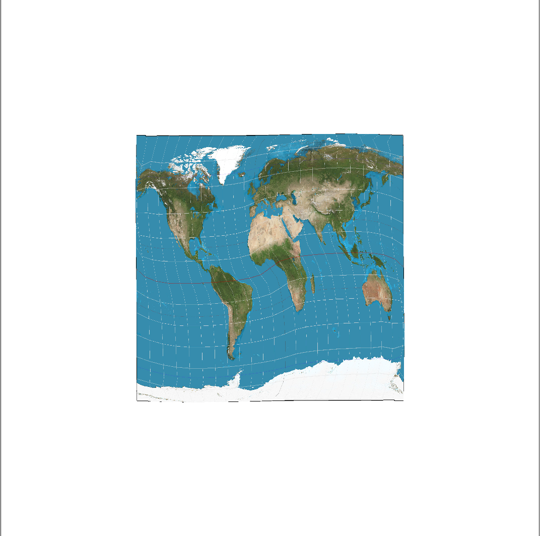
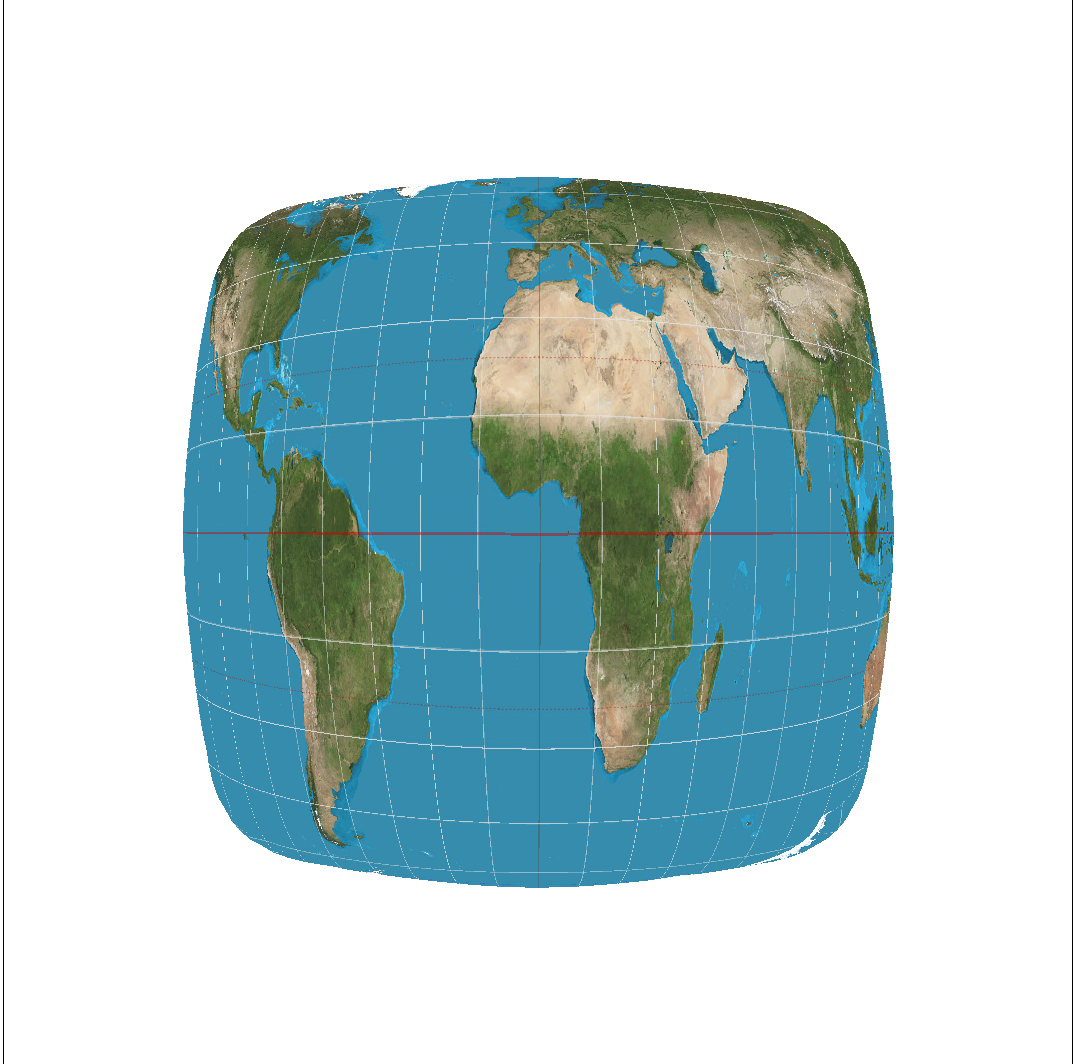
在命令行下输入./draw ../svg/texmap,运行结果如下
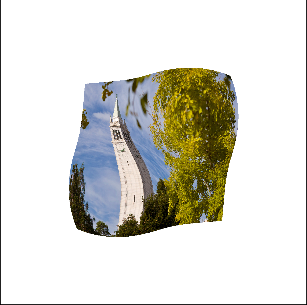
Part 6: “Level sampling” with mipmaps for texture mapping
题目介绍
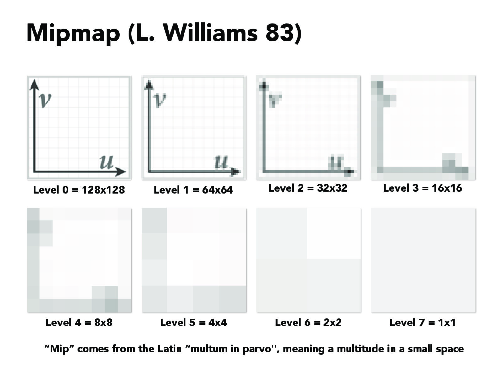
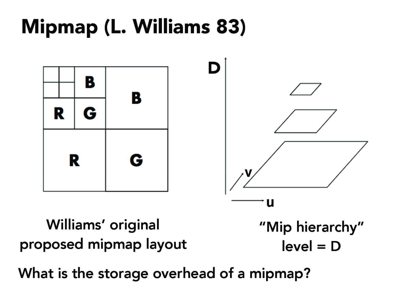
在上一题的基础上我们在加入level sampling,这里就需要提及一下mipmap技术了。这种技术是将纹理图片分成以一系列,比方说原纹理图是128x128的,那么我就要64*64,32x32,16x16…1x1一共7张图片。这么多图片用来干嘛呢?是为了加快渲染速度和减少图像锯齿,贴图被处理成由一系列被预先计算和优化过的图片组成的文件,这样的贴图被称为 MIP map 或者 mipmap,多级渐进纹理由一组分辨率逐渐降低的纹理序列组成,每一级纹理宽度和高度都是上一级纹理宽度和高度的一半。宽和高不一定相等,也就是说,这些纹理不一定都是正方形。
这里我转载一段别的博主的话关于mipmap的解释:
图形学中经常会用到z值来控制物体的远近,有时会在一个多边形中用z值变化来生成纵深感很强的物体,这时在一个多边形内部的纹理贴图就会用到不同的缩小比率,如果只用原始的纹理去采样,就会在缩小比率大的地方(通常是z值大的地方)出现混叠。1983年,Lance willians在他的论文“Pyramidal Parametrics”中提出了一种解决上述问题的方法。他将原始纹理逐步做下采样(即图像缩小),从而生成一系列的不同大小的纹理,这些纹理被称为mipmap,使用时按照缩小比率来选择合适大小的纹理。比如,我们要用做贴图的纹理大小为 64x32,对它做下采样生成32x16,16x8,8x4,4x2,2x1,1x1的纹理,如果要render的区域大小为14x6,那么我们要么选16x8的纹理贴,要么选16x8与8x4的两块纹理做完线形平均的结果贴。
作者:feixuedudiao
来源:CSDN
原文:https://blog.csdn.net/feixuedudiao/article/details/6233662
因此简单的说就是为了防止aliasing出现采用的一种新的采样技术。
实现原理
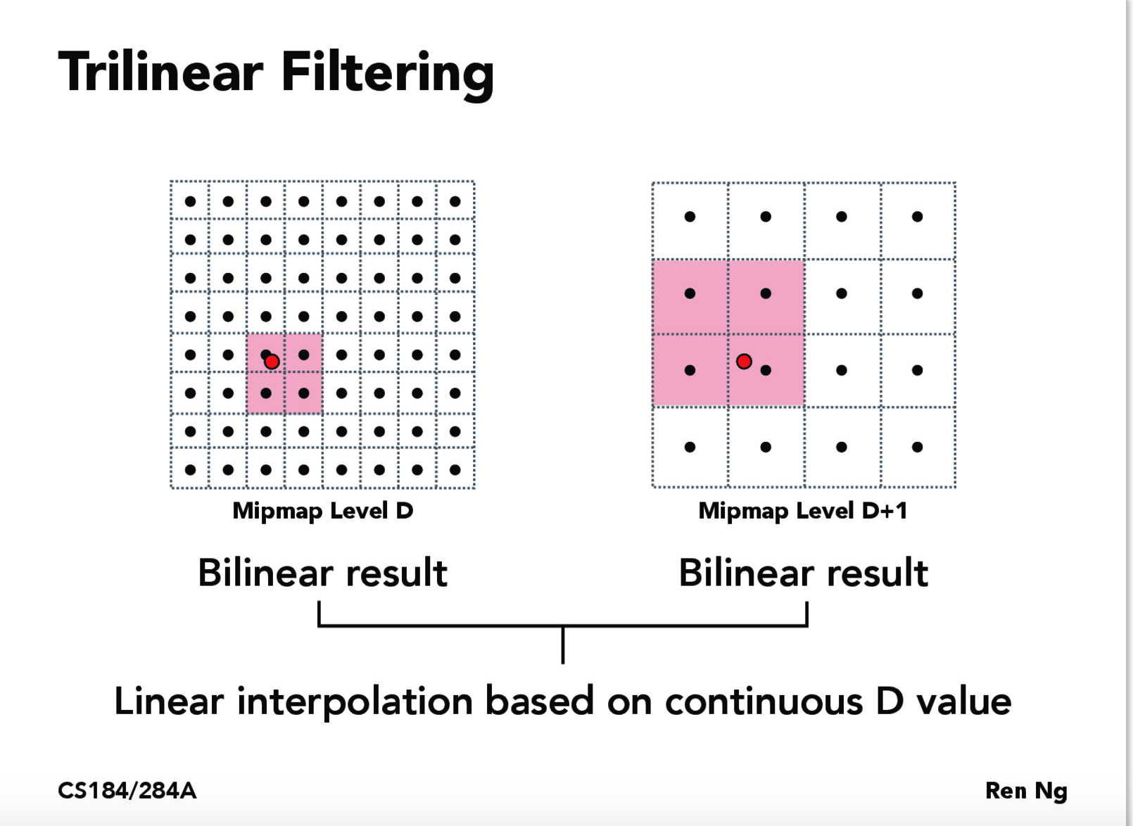
还记得上题中填充的lsm属性么,这个就是指定mipmap的level选择方式的。mipmap有两种选择方式,分别是nearest最邻近方法(又是你。。。)和linear线性插值法。最邻近方法就是我得到了一个level,比方说是1.2,由于level都是整数,因此我选择1,表明选择了原纹理贴图一半分辨率的纹理贴图,一个像素对应两个纹素。而linear插值方法则是获取像素在level = 1和level = 2的两个纹理贴图对应的纹理颜色之后再进行一次线性插值,如果此时我们选择的采样方式是双线性插值,那么实际上我们就进行了三次线性插值,这种方式也被称作三线性插值。
我们需要在上一题的基础上修改下列函数:
(1)DrawRend::rasterize_triangle
(2)TexTri::color
(3)Texture::sample
(4)Texture::get_level
首先修改DrawRend::rasterize_triangle
void DrawRend::rasterize_triangle( float x0, float y0,
                         float x1, float y1,
                         float x2, float y2,
                         Color color, Triangle *tri) {

  float xMax = std::max(x0, x1);
  xMax = std::max(xMax, x2);
  float yMax = std::max(y0, y1);
  yMax = std::max(yMax, y2);
  float xMin = std::min(x0, x1);
  xMin = std::min(xMin, x2);
  float yMin = std::min(y0, y1);
  yMin = std::min(yMin, y2);

  bool isBary = false;
  SampleParams sp;
  if(tri != nullptr)
  {
      isBary = true;
      sp.lsm = lsm;
      sp.psm = psm;
  }
  for (int x = (int)xMin; x <= (int)xMax; x++)
  {
      for (int y = (int)yMin; y <= (int)yMax; y++)
      {
          if (y < 0 || y >= samplebuffer.size() || x < 0 || x >= samplebuffer[y].size())
              continue;

          const SampleBuffer &p = samplebuffer[y][x];
          for(int sub_x = 0; sub_x < p.samples_per_side; sub_x++)
          {
            for(int sub_y = 0; sub_y < p.samples_per_side; sub_y++)
            {
              float centerLength = (1.0f / p.samples_per_side);
              float xCenter = x + centerLength * (sub_x + 1) - centerLength / 2;
              float yCenter = y + centerLength * (sub_y + 1) - centerLength / 2;

              if (inside_triangle(xCenter, yCenter, x0, y0, x1, y1, x2, y2))
              {
                  if(!isBary)
                      samplebuffer[y][x].fill_color(sub_x, sub_y, color);
                  else
                  {
                      float params[3] = {1, 1, 1};
                      if(!this->bary_coord(xCenter, yCenter, x0, y0, x1, y1, x2, y2, params))
                      {
                        samplebuffer[y][x].fill_color(sub_x, sub_y, color);
                        return;
                      }
                      Vector3D v3(params[0], params[1], params[2]);

                      float dx_params[3] = {1, 1, 1};
                      float dy_params[3] = {1, 1, 1};
                      float p_dx = xCenter + 1;
                      float p_dy = yCenter + 1;
                      if(!inside_triangle(xCenter + 1, yCenter, x0, y0, x1, y1, x2, y2))
                          p_dx = xCenter;
                      if(!inside_triangle(xCenter, yCenter + 1, x0, y0, x1, y1, x2, y2))
                          p_dy = yCenter;

                      this->bary_coord(p_dx, yCenter, x0, y0, x1, y1, x2, y2, dx_params);
                      this->bary_coord(xCenter, p_dy, x0, y0, x1, y1, x2, y2, dy_params);
                      Vector3D p_dx_bary(dx_params[0], dx_params[1], dx_params[2]);
                      Vector3D p_dy_bary(dy_params[0], dy_params[1], dy_params[2]);

                      Color cc = tri->color(v3, p_dx_bary, p_dy_bary, sp);
                      samplebuffer[y][x].fill_color(sub_x, sub_y, cc);
                  }
              }
            }
          }
      }
  }
}
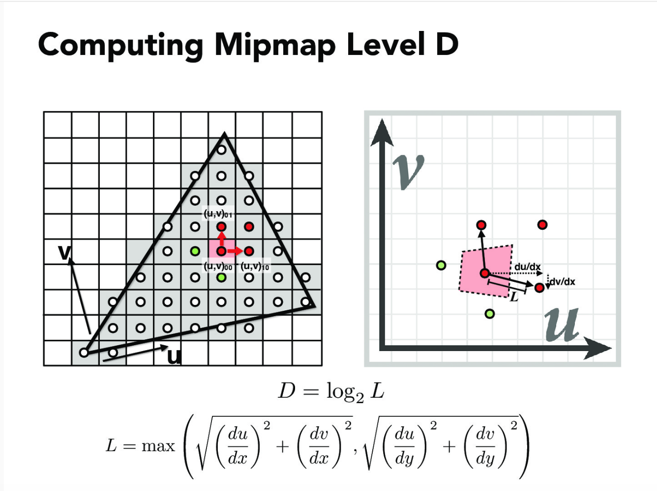
接着修改Texture::get_level函数,计算level层级。
/**
 * 获取的level是一个float类型的,之后会根据nearest还是linear来
 * 得到最终的值
 * @param sp
 * @return
 */
float Texture::get_level(const SampleParams &sp) {
  // 这是两个很小的向量(看作是向量微元)
  Vector2D dx_uv = sp.p_dx_uv - sp.p_uv;
  Vector2D dy_uv = sp.p_dy_uv - sp.p_uv;

  //L2是L的平方,而L就是一个pixel在纹理贴图中占据多少个texl
  Vector2D dx_uv_2(dx_uv.x * width, dx_uv.y *height);
  Vector2D dy_uv_2(dy_uv.x * width, dy_uv.y *height);
  float L2 = std::max<float>(dx_uv_2.norm2(), dy_uv_2.norm2());
  if(L2 <= 1)
    return 0;
  float levelD = log2(sqrt(L2));

  return levelD;
}再接着,修改我们上一问实现的Texture::sample函数。加入对于level选择方式的判断。
Color Texture::sample(const SampleParams &sp) {
float levelD = 0;
if(sp.lsm == L_ZERO)
{
if (sp.psm == P_NEAREST)
{
return this->sample_nearest(sp.p_uv, (int)levelD);
}
else
{
return this->sample_bilinear(sp.p_uv, (int)levelD);
}
}
else if(sp.lsm == L_NEAREST)
{
levelD = round(get_level(sp));
if (sp.psm == P_NEAREST)
{
return this->sample_nearest(sp.p_uv, (int)levelD);
}
else
{
return this->sample_bilinear(sp.p_uv, (int)levelD);
}
}
else
{
levelD = get_level(sp);
if (sp.psm == P_NEAREST)
{
Color c0 = this->sample_nearest(sp.p_uv, (int)floor(levelD));
Color c1 = this->sample_nearest(sp.p_uv, (int)ceil(levelD));
float factor;
float level_up = ceil(levelD);
float level_down = floor(levelD);
if(level_up == level_down)
factor = 0;
else
factor = (levelD - level_down) / (level_up - level_down);
Color final_color(c0 + (-factor * c0) + factor * c1);
final_color = Color(std::max<float>(0, final_color.r),
std::max<float>(0, final_color.g),
std::max<float>(0, final_color.b));
return final_color;
}
else {
return this->sample_bilinear(sp.p_uv, levelD);
}
}
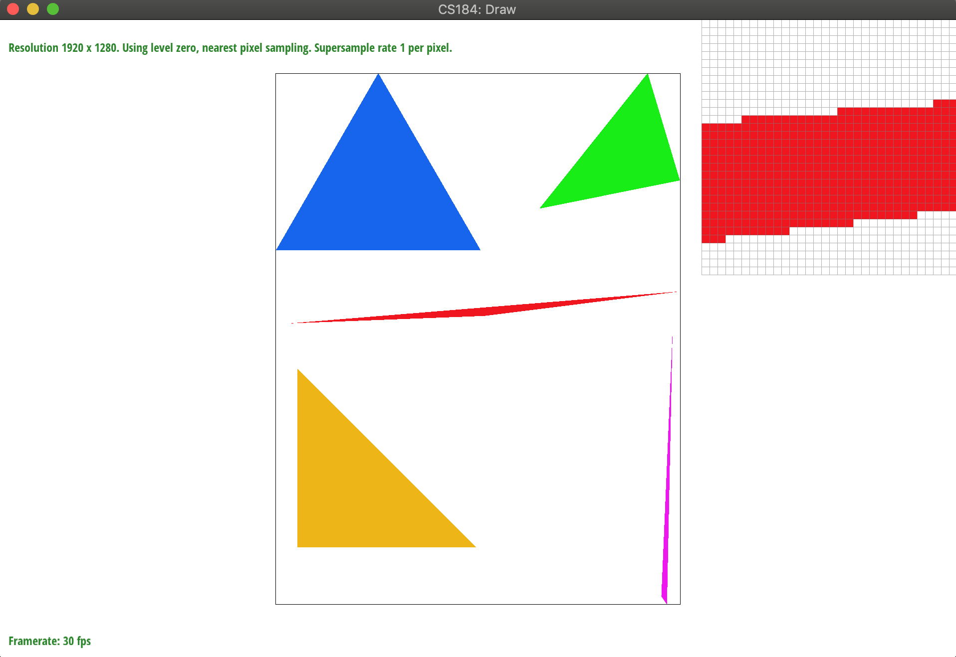
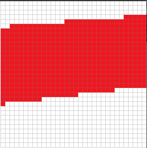
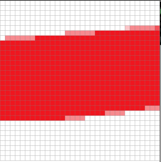
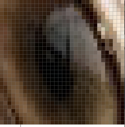
}OK完事了,运行一下结果区别如下.
level0下的最邻近采样和双线性采样
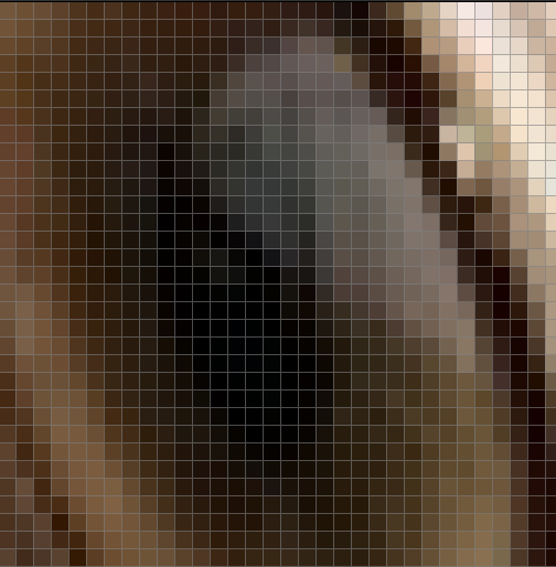
最邻近选择level下的最邻近采样和双线性采样
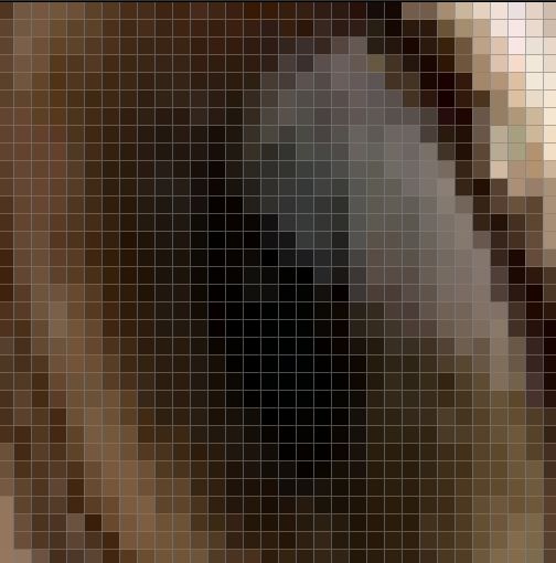
线性插值选择level下的最邻近采样和双线性采样
本博客所有文章除特别声明外,均采用 CC BY-SA 3.0协议 。转载请注明出处!